
IoT Based Weather Monitoring System Tutorial. Ever thought about how to check the real temperature and humidity in your yard, garden, or balcony? Phone weather apps help. Still, they show the general area data, not true conditions in your spot. Imagine creating a small smart device that can monitor the weather in your location. This gadget transmits data over the internet, which can be accessed from anywhere in the world at any time. Welcome to the fun world of IoT! This is a full guide to get you started. We will be building an IoT weather monitor step by step. Perfect for complete beginners, students, and hobbyists. Start with electronics, code, and cloud technologies. Complete with a live weather station, understand key IoT concepts as well. Time to begin! IoT Based Weather Monitoring System Tutorial.
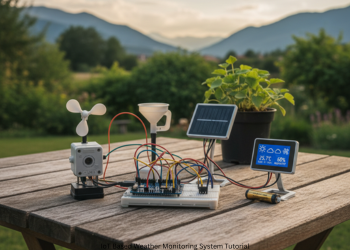
What We Build – Project Summary We create a setup that:
- Reads the air: A sensor checks temperature and humidity.
- Handles data: A microcontroller acts as the brain. It grabs sensor info.
- Links online: Built-in Wi-Fi joins your home network.
- Uploads to cloud: Sends temp and humidity to a free IoT site.
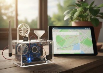
- Shows data: View graphs and charts on any browser worldwide. (Conceptual Image). IoT Based Weather Monitoring System Tutorial.
Part 1: Get Your Parts (Shopping List)
Few inexpensive items get the job done. Here is the list:
- NodeMCU ESP8266 Board: Main actor. Cheap. Has Wi-Fi. For IoT. Brain and network in one.
- DHT11 or DHT22 Sensor: Measures temp and humidity.
- DHT11 (Blue): Cheap. Good starting point. Fairly accurate.
- DHT22 (White): More expensive. Better range and accuracy. We use DHT11 here. Code fits DHT22 with small tweak.
- Breadboard: Hole grid board. Prototype circuits (no solder). Component playground. IoT Based Weather Monitoring System Tutorial.
- Jumper Wires (Male-Male): Short wires connect parts on board.
- Micro-USB Cable: Just like phone chargers. Powers NodeMCU. Uploads code from PC. That is all. Five things in total. IoT Based Weather Monitoring System Tutorial.
Part 2: The Circuit – Wire
It Up Hardware comes alive now. Easier than it seems. Three links join NodeMCU and DHT11. IoT Based Weather Monitoring System Tutorial.
Identify DHT11 pins. Three major ones are:
- VCC or +: Power.
- DATA or OUT: Sends readings.
- GND or -: Ground.
Link to NodeMCU with wires.
Wire Guide:
- DHT11 GND to NodeMCU GND. DHT11 VCC to NodeMCU 3V3.
- Gives sensor 3.3 volts. DHT11 DATA to NodeMCU D4. Pin for data reads. Make sure to double check. Most problems are from bad wires. Setup looks like this:
- DHT11 Pin NodeMCU Pin GND (-) GND VCC (+) 3V3 DATA (OUT) D4. IoT Based Weather Monitoring System Tutorial.
Part 3: Prep Software Setup Hardware set.
Now ready your PC for NodeMCU code.
Step 1: Add Arduino IDE
Free tool writes and sends code to boards like NodeMCU.
- Go to arduino.cc/en/software.
- Download version for your OS: Windows, Mac, Linux.
- Install it.
Step 2: Set IDE for NodeMCU IDE misses NodeMCU at first.
Add files.
- Launch IDE.
- File > Preferences.
- Paste in Additional Boards Manager URLs: http://arduino.esp8266.com/stable/package_esp8266_index.json
- Hit OK. Tools > Board > Boards Manager.
- Search esp8266. Pick “esp8266 by ESP8266 Community.”
- Install. Wait minutes. Close window.
Step 3: Add Libraries
Packs of code make sensor use easier. For DHT, need two:
- Tools > Manage Libraries.
- Search DHT sensor library by Adafruit. Install.
- OK deps like Adafruit Unified Sensor. Install all.
- Ready to code!
Part 4: Cloud-ThingSpeak Setup
Need a place for data to go live. ThingSpeak is free. Accommodates IoT data, graphs, and analytics. IoT Based Weather Monitoring System Tutorial.
- Sign Up: thingspeak.com.
- New account. New Channel: Stores data.
Log in. Channels > My Channels. New Channel.
Set It:
- Name: My Home Weather Station.
- Description: Short note.
- Field 1: Temperature.
- Field 2: Humidity. Holds our data. Save.
API Keys:
- Key step. Key lets device post data.
- API Keys tab. Copy Write API Key. Save safe, like notepad. Use in code. Note Channel ID at top. IoT Based Weather Monitoring System Tutorial.
Part 5: The Code (Core Part)
Tell NodeMCU its job. Open Arduino IDE. File > New. Paste this code.
Part 6: Upload, Test, and Visualize!
This is the big moment.
- Select Board Open Arduino IDE, go to Tools > Board, then select NodeMCU 1.0 (ESP-12E Module).
- Select Port Connect your NodeMCU using a micro-USB cable and go to Tools > Port. Now select the appropriate COM port for Windows, or /dev/cu.usbserialfor Mac.
- Upload Code Click the upload icon. The icon looks like a right-pointing arrow in Arduino IDE. It compiles the code and uploads it into NodeMCU. Wait for about one minute.
- Serial Monitor Once the upload has completed, click on the magnifying glass icon located at the top right corner. Then open Serial Monitor and set the baud rate to 115200. You should see messages : First: “Connecting to [Your WiFi].”, then “WiFi connected!”. Next, you will see temperature and humidity reads. Lastly, you’ll see “Channel update successful.”. IoT Based Weather Monitoring System Tutorial.
- View Your ThingSpeak Channel Go to your ThingSpeak page again. Click the Private View tab. After a minute or two, you will be able to view data on the charts. Charts refresh every time your device sends new information. Congratulations! You just created a working IoT Weather Station. You can view your ThingSpeak link from anywhere, anytime for local weather information. IoT Based Weather Monitoring System Tutorial.
Conclusion
Next Steps You just took your first step into IoT. You wired a sensor to a microcontroller. You coded data reads. You connected to the internet. You sent data to the cloud for charting. IoT Based Weather Monitoring System Tutorial.
FAQs
Q1: Upload of code fails. Error says “espcomm_upload_mem failed” or “failed to connect”.
A: Common problem. Check these in order:
Right Port: In Tools > Port, select the appropriate one. Unplug NodeMCU. Observe which port disappears and then reappears. USB Cable: Some cables charge only, no data. Use a data cable such as one for a phone. Drivers: NodeMCU might use CH340 chip. Download “CH340 driver” for your OS. Install it. Flash Button: Unplug board. Hold FLASH or BOOT button. Plug it back. Hold it until upload starts. Then releas
Q2: Serial Monitor says “Failed to read from DHT sensor!” or shows “nan”.
A: NodeMCU misses DHT11 signal.
Wiring Check: Most times it’s wires. Verify that GND goes to GND, VCC goes to 3V3, and DATA goes to D4. Retighten any loose wires. Code Pin: ‘#define DHTPIN D4’ should be matching your DATA wire pin. Bad Sensor: Sometimes a cheap DHT11 sensor fails. Swap it out if you have spare. Power Pin: Use 3V3, Not Vin.
Q3: Can I swap DHT22 for DHT11?
A: Yes. The DHT22 works better. Same wires. Edit code line: #define DHTTYPE DHT11 To: #define DHTTYPE DHT22 Re-upload. Done.
Q4: Can I run on battery, not computer?
A: Yes, Use 5V on Vin. Like power bank. For lasting power look at LiPo and boards. Basically, ESP8266 eats power if WiFi is on. Deep sleep helps the battery. That’s next level
Q5: Temperature reads too high. Why?
A: The sensor captures the heat from the NodeMCU chip. It warms up. Solution: Longer wires, take the sensor away. It reads real air temperature.
1 thought on “IoT Based Weather Monitoring System Tutorial”